Electrical Measurement
| Detection Parameter | RMS Current |
| Sampling Frequency | 3.3 kHz |
| Working Frequency | 50~60 Hz |
| Rated Primary Current (Per CT) | 300 Arms |
| Rated Secondary Current | 150 mArms |
| Minimum Reporting Current1 | 3Arms (1min Interval) 2.5Arms (10min Interval) |
| Accuracy | ±1 % |
| Resolution | 1 mA |
| Temperature Sensor | Sensor type: 1 × NTC Sensor Measuring range: -20°C ~ 100°C Measuring accuracy: ±1 % |
| Wireless Transmission | |
|---|---|
| Protocol | LoRaWAN® |
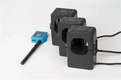
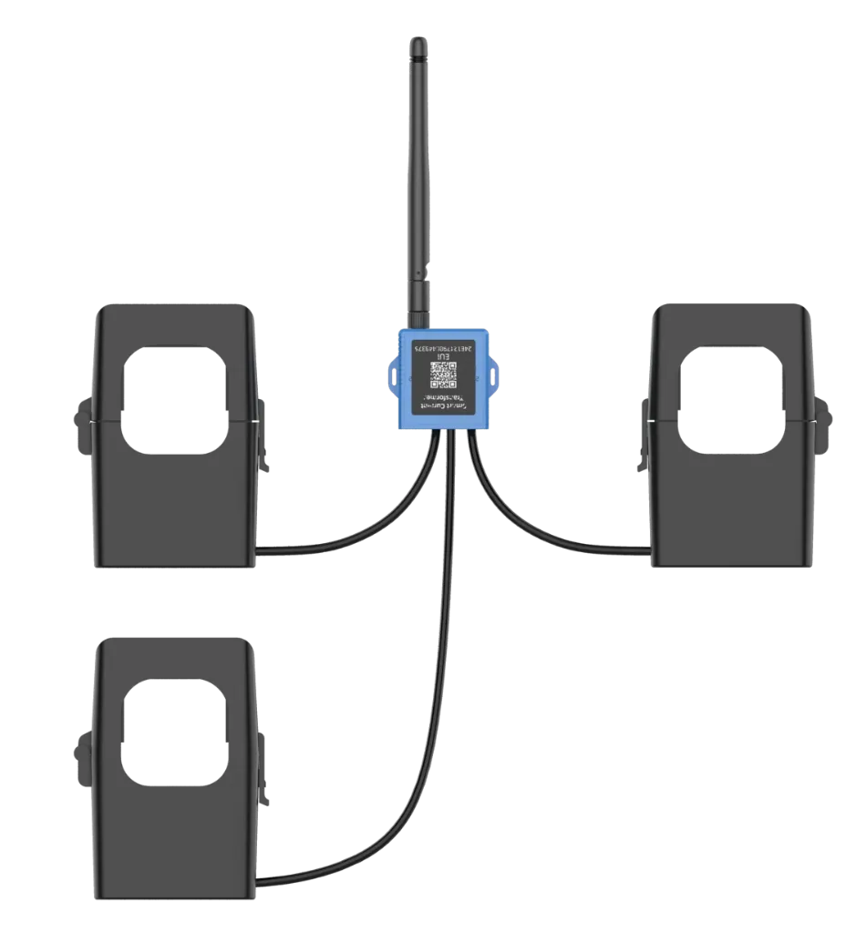
| Antenna Connector | 1 × 50 Ω SMA Connector (Center PIN: SMA Female) |
| Frequency | CN470/IN865/RU864/EU868/US915/AU915/KR920/AS923-1&2&3&4 |
| Tx Power | 16 dBm (868 MHz)/20 dBm (915 MHz)/19 dBm (470 MHz) |
| Sensitivity | -137dBm |
| Mode | OTAA/ABP Class A |
| Others | |
| Button | 1 × Reboot Button |
| LED Indicator | 1 × Status/Alarm Indicator |
| Port | 1 × USB Type-C for Power Supply, Configuration, Console or Cable Temperature Sensor Connection |
| Software | |
| Configuration | USB Type-C or Downlink |
| Advanced Feature | Threshold Alarm, Overrange Alarm, FUOTA |
| Physical Characteristics | |
| Power Supply | 1. Induced current power supply2 2. 5V by USB Type-C Port |
| Insulation Voltage | 3kVac(r.m.s)(1mA/1min) |
| Color/ Material | Blue, PBT+PC (UL94 V0) |
| Cable Length | 1m |
| Operating Temperature | Transceiver: -20°C~70°C (-4°F~158°F) CT Clamp: -40°C~55°C (-40°F~131°F) |
| Storage Temperature | Transceiver: -25°C~80°C (-13°F~176°F) CT Clamp: -40°C~55°C (-40°F~131°F) |
| Relative Humidity | ≤ 95% (Non-condensing) |
| Ingress Protection | IP30 |
| Dimensions | Transceiver: 38 × 34.5 × 16 mm (1.5 × 1.36 × 0.63 in) CT Clamp:56.5 × 36.5 × 68.5 mm (2.24 × 1.44 × 2.70 in) Wire Hole: Ф 24.2 mm(Ф 0.95 in) |
| Weight | Transceiver: 13.05 g Per CT Clamp: 250 g |
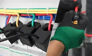
| Installation | Transceiver: Cable-tie Mounting (under integrated mode) CT Clamp: Suspended on the Testing Conductor |
| Approvals | |
| Regulatory | CE, FCC, UL508 |
1The minimum current to report data under different reporting intervals when the device is powered by the testing conductor. To measure lower currents, the device must be powered via USB.
2When the device is powered by the testing conductor, it can only be powered by phase A wire.